Three years ago - in 2017 - the line of of LLC NIK-ELEKTRONIKA main products - energy meters (electricity, water, heat, gas) was replenished with the next product of widespread use - current transformers of a new design.
Current transformer is an instrument transformer in which the secondary current, under normal conditions of use, is proportional to the primary current. The primary windings of the current transformers are connected in a gap of the line conductors.
Instrument transformers, including current transformers, are designed to reduce primary currents to levels convenient for connection to measuring instruments. They also provide separation between high and low voltage circuits, making them relatively safe for maintenance personnel.
Our current transformers are used in low voltage switchgear and are designed to transmit analog signals to the measuring devices, meters and have one secondary winding. Transformers are used in metering systems, including commercial, of electrical energy. Although the principle of operation of current transformers does not depend on the voltage where they are used in, voltage of the network significantly affects the requirements for the insulation of the windings, and, accordingly, on their design.
In our version, the current transformer is a single-layer winding on a toroidal magnetic core made of nanocrystalline alloys. Nanocrystalline alloys are a new class of soft magnetic materials, distinguished by their manufacturability and relative cheapness of raw materials. Due to the structural feature of the alloy, a high magnetic permeability is achieved, as well as low eddy current losses and excellent magnetic permeability characteristics. The winding on the toroidal magnetic core is the secondary winding, and the primary winding is the bus, passed through the toroid hole. Primary bar is swivel in TOPN-0.66 or non-swivel in TOPNШ-0.66. Аn alternating current which is passed through the primary winding, create an alternating magnetic flux in the magnetic core, which will induce an electromotive force in the secondary winding.
Current transformers manufactured at our factory in Dnipro city, intended for the transmission of a signal of measuring information to measuring instruments and devices in AC installations with a frequency of 50 Hz with a rated voltage of up to 0.66 kV inclusively at electric power facilities, agriculture, in the communal sector and organizations of other sectors of the national economy.
The TOPN transformer (TOPN-0.66) meets the requirements of the following standards:
- DSTU IEC 60044-1: 2008 “Measuring transformers. Part 1. Current transformers (IEC 60044-1: 2003, IDT)" including:
- insulation of the primary winding (primary circuit) of the transformer withstands the action of a test voltage of 3 kV with a frequency of 50 Hz for 60 s
- the rated withstand voltage of 50 Hz for the isolation of the secondary winding of transformers is 3 kV
- the rated withstand voltage for the turn-to-turn insulation of the transformer is 4.5 kV (peak value)
- insulation resistance of the transformer windings under normal climatic conditions not less than:
- 40 MOhm for primary winding
- 20 MOhm for the secondary winding. - GOST 15150-69 “Machines, devices and other technical products. Versions for different climatic regions. Categories, conditions of operation, storage and transportation in terms of the impact of climatic factors of the external environment" in terms of climatic factors for operation in areas related to climatic design. Location category 3
- GOST 17516.1-90 “Electrical products. General requirements in terms of resistance to mechanical external factors "in terms of resistance to mechanical factors of the external environment, according to the group of mechanical performance M39 degree of severity 8
Protection against interference in the design of transformers is carried out by sealing the transformer case, as a result of which access to the elements of the transformer is impossible without damaging the seals. - Main technical characteristics
Rated voltage - 0.66 kV.
Maximum operating voltage - 0.72 kV.
Rated primary current - 150 A; 200 A; 300 A; 400 A; 500A; 600 A; 800 A; 1000 A; 1200 A; 1500 A; 2000 A.
Rated frequency - 50 Hz.
Rated current in secondary winding - 5 A.
Accuracy class of the secondary winding in accordance with GOST IEC 60044-1 - 0.5S.
Rated power of the secondary winding (cos φ = 0.8) - 5 V A.
Nominal safety factor of secondary winding devices - 3.
Operating temperature range - from minus 45 ⁰С to plus 40 ⁰С.
The primary winding of the transformer is a rotary bus (TOPN-0.66) or non-rotary (TOPNШ-0.66).
Overall dimensions of transformers:
with a rated primary current of 150, 200, 300 and 400 A - no more than 125 x 98 x 75 mm
with a rated primary current of 500 A, 600 A - no more than 170 x 98 x 75 mm
with a rated primary current of 800 A, 1000 A, 1200 A, 1500 A and 2000 A - no more than 180 x 66 x 170 mm
The mass of transformers - no more than 0.7 kg (at primary currents of 150 - 400 A), 1.0 kg (at primary currents of 500 - 600A) and 1.5 kg (at primary currents of 800 - 2000A)
MTBF is at least 3 × 10⁵ hours.
Average service life is at least 25 years. - An example of writing a symbol for a transformer for a rated voltage of 0.66 kV when ordering it:
Current transformer ТОPN -0,66-0,5S-600/5 У3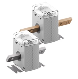
![]()
Т - transformer
О - supporting in a plastic case
Р - rotary bus
N - NiK trade mark
rated voltage 0,66 кВ
rated primary current 600 А
rated secondary current 5 А
accuracy class 0,5S
climatic version У
placement category 3